SQUID NMR TECHNIQUES
H.M. Bozler, Jinshan Zhang, Yuan Gu, K.S.White, C.M. Gould,
Department of Physics and Astronomy
* Supported by NSF grant DMR-9973255.
SQUID amplifiers are intrinsically wide band and low noise. The advantage of using such amplifiers for NMR becomes substantial at low frequencies or where signals are extremely broad. Both of these regimes are relevant to studying 3He monolayers on graphite. Recent experiments on 3He monolayers in our laboratory have used the apparatus described here. This apparatus is essentially an improved version of the system developed by Friedman et al. at USC.
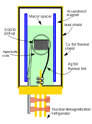
The use of a SQUID amplifier requires the careful shielding of all parts of the electronics. In addition, the amplifier easily picks up any fields produced by magnets and leads. Eddy currents produced by normal metals can produce very large background signals, and without a large effort, those signals can easily exceed the slew rate of the SQUID. The figure at the top shows a schematic of the experimental cell. The entire experimental region is surrounded by a lead shield. A pickup coil surrounds the sample and an orthogonal pair of Helmholtz coils is used to produce a tipping field. The static magnetic field is produced by "sandwich" superconducting magnet.This magnet is made by machining a pure aluminum mandrel and a closely fitted outer aluminum sleeve between which a superconducting coil and a distributed heater wire is wound.
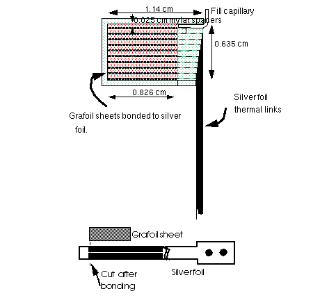
The grafoil sample which is shown schematically above is thermally connected to the nuclear demagnetization refrigerator with silver foils that are diffusion bonded to the grafoil. In order to to reduce eddy currents, the silver foils have been lithographically formed into small wires which are kept seperated throughout the region where there is a significant time varying magnetic field.
The configuration of the SQUID electronics is similar to the one used in our earlier work, except that we have both diode switches and a 10 ohm resistor for either pulsed or CW NMR. All of the low temperature electronics are enclosed in solid superconducting sheilds. We are currently using a Quantum Designs SQUID, however, this system reduces our useful bandwidth and we replacing it with a SQUID system designed with our collaboration with TRW.
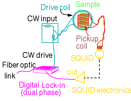
The electronics for pulsed NMR for pulsed and CW NMR are shown schematically above.
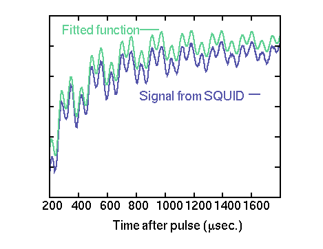
The figure above shows a typical NMR signal observed with a submonolayer of 3He. In addition to an exponential background (caused by eddy currents) there is an obvious beating signal which is caused by the very different Larmor frequencies of 3He and 13C. The NMR signal can be fitted extremely well with: a) an exponentially decaying background,; b) an exponentially decaying signal at the 3He Larmor frequency, and c) an expenentially decaying signal at the precise ratio of Larmor frequencies to be consistent with 13C.
The 13C signal has not generally been observed in this system, however its spectral weight is in reasonable agreement with what one would expect assuming the normal abundance of 13C. We do not have T1 data for 13C at this time. The decay time is probably limited by the homogeneity of the static field. We have shown that the amplitude of this signal follows the Curie Law down to 0.3 mK, allowing us totake advantage of it as a way of confirming temperatures in systems with low coverages.
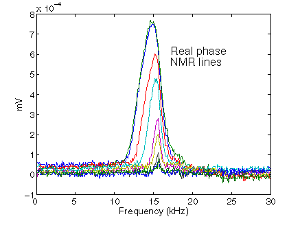
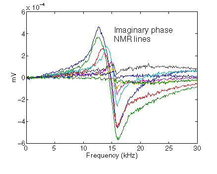
We also observe CW NMR signals. Below we show a few examples which were obtained from 3He at ferromagnetic coverages.
